Motor Eaton 3933 4633 5433 6433 7630 Pump Eaton 3923 4623 5423 6423 7620 7640
Eaton ACA Pump Technical Data
Table of values (theoretical values)
Eaton ACA pump
|
Eaton 3923
|
Eaton 4623
|
Eaton 5423
|
Eaton 6423
|
Eaton 7620
|
|
Displacement
|
in3/rev
|
3.89
|
4.6
|
5.44
|
6.44
|
7.62
|
|
cm3/rev
|
63,7
|
75,3
|
89,1
|
105,5
|
124,8
|
|
Maximum Shaft Speed
|
Rpm @ 18°
|
4160
|
4160
|
3720
|
3720
|
2775
|
|
Nominal Pressure
|
psi
|
6000
|
6000
|
6000
|
6000
|
6000
|
|
(bar)
|
(420)
|
(420)
|
(420)
|
(420)
|
(420)
|
|
Peak Pressure
|
psi
|
7000
|
7000
|
7000
|
7000
|
7000
|
|
(bar)
|
(480)
|
(480)
|
(480)
|
(480)
|
(480)
|
|
Output Flow
|
g/m @3500 psi
|
67.3
|
79.2
|
84.1
|
99.1
|
87.9
|
|
l/m @241 bar
|
255
|
300
|
318
|
375
|
333
|
|
Input Torque
|
lb-in @3500 psi
|
2346
|
2786
|
3285
|
3900
|
4552
|
|
Nm @241 bar
|
265
|
315
|
371
|
441
|
514
|
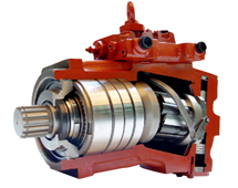
Eaton heavy duty variable pump
The Eaton heavy duty variable displacement pump contains a rotating cylinder barrel and pistons. The displacement control directs control pressure to the two servo pistons that position the swash plate. The variable pump is powered into stroke and springs, on the servo pistons, bring it out of stroke. The swash plate pivots on tapered roller bearings. A bolt-on charge pump, with a cartridge type charge pressure relief valve, is available in four displacements. One lever controls direction, varies speed and provides dynamic braking. This ease of operation, in conjunction with a wide variety of control options, allows Eaton hydrostatic transmissions to be readily adapted to many applications.
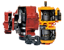
Power Limiter Valve Operation
Power limiter valves (PLV) are high pressure relief valves built into the pump’s end cover. When pressure in the high pressure loop gets too high, the PLV opens to the pump case. Besides an immediate drop in the loop high pressure, the open PLV also causes control pressure to drop. This in turn allows the centering springs on the servo pistons to bring the pump out of stroke until the pressure drops to the relief valve setting and the PLV closes. The PLV will also act as a check valve to prevent cavitations in the event of a rapid pressure rise and hose expansion. A motor with integral shuttle valve is used in conjunction with the power limiter valve pump.
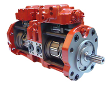
Tandem Pump Applications
Tandem pumps are most typically used in applications where two independent sources of hydraulic power are required while taking advantage of using only one power source to drive the two pumps. This saves on the expense of driving two pumps by eliminating the split drive gear box or eliminating another power source such as a second engine or motor. Tandem pumps can be used on machines such as track drive equipment where independent power is required at each track. Speed and power can be controlled to each side of the vehicle for steering and vehicle speed control both in forward and reverse directions. Tandem pumps can also be used to create the equivalent flow of one larger displacement pump by combining the flows of the two pumps. This is an economic advantage over using a single large displacement pump. Tandem pumps may also be used in industrial, construction or mining applications where several sources of hydraulic power are required while taking advantage of using only one power source to drive the two pumps.
The variable displacement pump provides a flow of high pressure oil. Pump output flow can be varied to obtain the desired motor output speed. For example, when the pump’s displacement is zero, no oil is pumped and the transmission’s motor output shaft is stopped. Conversely, maximum pump displacement produces maximum motor shaft speed. The direction of high pressure flow can also be reversed; doing so reverses the direction the motor output shaft rotates. A charge pump is integrated into the piston pump and driven by the shaft of the piston pump. The drawing illustrates a suction filtration circuit. Eaton recommends a suction filter without a bypass valve. The charge pump has a Low Pressure Relief Valve.
Performance – Charge Pump
Eaton offers a choice of four charge pump displacements to go with their heavy duty transmission. These charge pumps are available with one or more of the following options: a pressure sensing port, remote pressure side filter ports; a spin-on pressure side filter; mounting flanges for auxiliary pump. An internal charge relief valve regulates charge pressure. Charge pressure supplies the control with pressure to operate the swash plate and to maintain a minimum pressure in the low side of the transmission loop.
The charge pressure setting is referenced to case pressure. Charge pressure is the differential pressure above case pressure.
Minimum charge pressure is the lowest pressure allowed to maintain a safe working condition in the low side of the loop. Minimum control pressure requirements are a function of speed, pressure, and swash plate angle, and may be higher than the minimum charge pressure shown in the Operating parameters tables. Maximum charge pressure is the highest charge pressure allowed by the charge relief adjustment, and which provides normal component life. Elevated charge pressure can be used as a secondary means to reduce the swash plate response time. At normal operating temperature charge inlet pressure must not fall below rated charge inlet pressure (vacuum). Minimum charge inlet pressure is only allowed at cold start conditions. In some applications it is recommended to warm up the fluid (e.g. in the tank) before starting the engine and then run the engine at limited speed. Maximum charge pump inlet pressure may be applied continuously.
Temperature and Viscosity
Temperature: The high temperature limits apply at the hottest point in the transmission, which is normally the motor case drain. The system should generally be run at or below the quoted rated temperature.
The maximum intermittent temperature is based on material properties and should never be exceeded.
Cold oil will generally not affect the durability of the transmission components, but it may affect the ability of oil to flow and transmit power; therefore temperatures should remain 16 °C [30 °F] above the pour point of the hydraulic fluid. The minimum temperature relates to the physical properties of component materials. Size heat exchangers to keep the fluid within these limits. Viscosity: For maximum efficiency and bearing life, ensure the fluid viscosity remains in the recommended range.
The minimum viscosity should be encountered only during brief occasions of maximum ambient temperature and severe duty cycle operation. The maximum viscosity should be encountered only at cold start.
Filtration System
To prevent premature wear, ensure only clean fluid enters the hydrostatic transmission circuit. A filter capable of controlling the fluid cleanliness to ISO 4406 class 22/18/13
(SAE J1165) or better, under normal operating conditions, is recommended. These cleanliness levels cannot be applied for hydraulic fluid residing in the component housing/case or any other cavity after transport. The filter may be located on the pump (integral) or in another location (remote). The integral filter has a filter bypass sensor to signal the machine operator when the filter requires changing. Filtration strategies include suction or pressure filtration. The selection of a filter depends on a number of factors including the contaminant ingression rate, the generation of contaminants in the system, the required fluid cleanliness, and the desired maintenance interval. Filters are selected to meet the above requirements using rating parameters of efficiency and capacity. Filter efficiency can be measured with a Beta ratio¹ (βX). For simple suction-filtered closed circuit transmissions and open circuit transmissions with return line filtration, a filter with a β-ratio within the range of β35-45 = 75 (β10 ≥ 2) or better has been found to be satisfactory. For some open circuit systems, and closed circuits with cylinders being supplied from the same reservoir, considerably higher filter efficiency is recommended. This also applies to systems with gears or clutches using a common reservoir. For these systems, a charge pressure or return filtration system with a filter β-ratio in the range of β15-20 = 75 (β10 ≥ 10) or better is typically required.
Control Options – Pump Electronic Proportional Displacement Control with Swashplate Mechanical Feedback
The Electronic Proportional displacement control is ideal for applications requiring electronic pump displacement control. The EP displacement control has been designed to withstand the rigors of off-highway equipment environmental conditions.
PumpElectronic ProportionalDisplacement Control withSwashplate Mechanical andElectronic Sensor Feedback
The Electronic Proportional displacement control with both swash plate mechanical and electronic sensor feedback is ideal for applications requiring both precise electronic pump displacement control and inherently safe operation. The dual feedback enables safety integrity level (SIL) compliance.
Standard Control with Neutral Lock-out
The neutral lock-out feature is an electrical switch that is closed when the transmission is in neutral. This switch can be used to prevent the activation of certain functions that require the pump to be in neutral. The lock-out feature is commonly used to prevent starting the prime mover or activating auxiliary functions. The electrical switch is available as normally open or normally closed.
Remote Pressure override
The remote pressure override control provides a means to remotely adjust the pressure setting of the pressure override valve.
This control may be used in applications requiring variable system pressure protection to prevent overloads and excessive heat generation. This valve operates similarly to the IPOR control.
De-stroke Control
The heavy duty De-stroke Control is a solenoid valve mounted on the standard variable pump control.
When energized, the valve cross-ports control pressure allowing centering springs to bring the pump out of stroke. It can be energized with a single switch, push button, or dead man’s switch. The solenoid coils are available in 12 volt or 24 volt DC and normally open and normally closed configurations.
Component Descriptions
A typical heavy duty hydrostatic transmission. The axial piston pump and axial piston motor are the main components. The filter, reservoir, heat exchanger, and oil lines make up the rest of the system. The function of each of these components is described: A separate energy source, such as an electric motor or internal combustion engine, turns the input shaft of the pump.
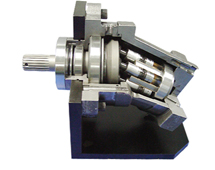
Variable Displacement Axial Piston Pump
The variable displacement pump provides a flow of high pressure oil. Pump output flow can be varied to obtain the desired motor output speed. For example, when the pump’s displacement is zero, no oil is pumped and the transmission’s motor output shaft is stopped. Conversely, maximum pump displacement produces maximum motor shaft speed. The direction of high pressure flow can also be reversed; doing so reverses the direction the motor output shaft rotates.
A charge pump is integrated into the piston pump and driven by the shaft of the piston pump. The drawing illustrates a suction filtration circuit. Eaton recommends a suction filter without a bypass valve. The charge pump has a Low Pressure Relief Valve that regulates the output pressure. Power limiter valves and high pressure relief valves are available as options.
Fixed Displacement
Axial Piston Motor The motor uses the high pressure oil flow from the pump to produce transmission output. The high pressure oil comes to the motor through one of the high pressure lines. It enters the motor, turns the output shaft, and then returns to the pump. Eaton piston motor integrates a hot oil shuttle and low pressure relief valve into the end cover. The shuttle valve and low pressure relief valve direct excess charge pump flow into the motor case. The shuttle valve is activated by high pressure and directs excess charge pump flow over the low pressure relief valve. This flushing action allows the charge pump to provide clean, cool oil to the closed loop circuit.
Eaton HHD motor Technical Data
Table of values (theoretical values)
Eaton HHD motor
|
Eaton 3933
|
Eaton 4633
|
Eaton 5433
|
Eaton 6433
|
Eaton 7630
|
|
Displacement
|
in3/rev
|
3.89
|
4.6
|
5.44
|
6.44
|
7.62
|
|
cm3/rev
|
63,7
|
75,3
|
89,1
|
105,5
|
124,8
|
|
Nominal Pressure
|
psi
|
6000
|
6000
|
6000
|
6000
|
6000
|
|
(bar)
|
(420)
|
(420)
|
(420)
|
(420)
|
(420)
|
|
Peak Pressure
|
psi
|
7000
|
7000
|
7000
|
7000
|
7000
|
|
(bar)
|
(480)
|
(480)
|
(480)
|
(480)
|
(480)
|
|
Maximum
|
rpm @ 18°
|
4160
|
4160
|
3720
|
3720
|
2775
|
|
Shaft Speed
|
rpm @ 10°
|
5380˜
|
5380˜
|
4810˜
|
4810˜
|
3425˜
|
|
Maximum
|
lb-in
|
3511
|
4149
|
4916
|
5807
|
6911
|
|
Output Torque
|
Nm
|
397
|
469
|
556
|
656
|
781
|
The motor uses the high pressure oil flow from the pump to produce transmission output. The high pressure oil comes to the motor through one of the high pressure lines. It enters the motor, turns the output shaft, and then returns to the pump. Eaton piston motors integrate a hot oil shuttle and low pressure relief valve into the end cover. The shuttle valve and low pressure relief valve direct excess charge pump flow into the motor case. The shuttle valve is activated by high pressure and directs excess charge pump flow over the low pressure relief valve. This flushing action allows the charge pump to provide clean, cool oil to the closed loop circuit.
|
Eaton pump part number
|
Eaton motor part number
|
|
3923-002
|
5423-367
|
4623-231
|
6423-081
|
4623-002
|
7620-094
|
3933-001
|
5433-080
|
4633-047
|
4633-190
|
|
3923-003
|
5423-402
|
4623-294
|
6423-279
|
4623-003
|
7620-316
|
3933-002
|
5433-087
|
4633-111
|
6433-002
|
|
3923-200
|
5423-417
|
4623-396
|
6423-338
|
4623-115
|
7640-032
|
3933-092
|
5433-116
|
4633-132
|
6433-009
|
|
3923-210
|
5423-493
|
4623-432
|
6423-449
|
5423-295
|
7620-039
|
3933-095
|
5433-138
|
4633-139
|
6433-011
|
|
3923-282
|
5423-518
|
4623-472
|
6423-511
|
6423-034
|
5423-004
|
4633-002
|
5433-142
|
4633-143
|
6433-042
|
|
3923-295
|
5423-715
|
4623-503
|
7620-000
|
6423-071
|
7620-058
|
4633-010
|
5433-203
|
4633-153
|
6433-107
|
|
3923-303
|
5423-867
|
4623-524
|
7620-001
|
6423-073
|
5423-016
|
4633-029
|
5433-205
|
5433-005
|
6433-120
|
|
3923-352
|
5423-889
|
4623-552
|
7620-010
|
7620-371
|
5423-003
|
4633-036
|
5433-216
|
5433-008
|
6433-154
|
|
3923-355
|
6423-005
|
4623-553
|
7620-011
|
4623-654
|
7620-037
|
4633-045
|
4633-164
|
7630-014
|
6433-187
|
|
3923-371
|
6423-020
|
4623-608
|
|
|
|
|
|
|
|